Posts

Recent Photos

Image
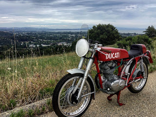
 Tank has been painted red, original steel fenders were installed and I swapped in a period Oldani magnesium front brake.

Finished

Image

Getting There...

Image
Finally finished mounting the seat cowl...I can now see how much room I have to play with underneath for mounting the ignition coil & control box.

Seat Cowl

Image
I've been test-fitting the seat cowl, and I also installed the hand-shaped aluminum 'skeleton" that will provide support from the inside. I drilled & tapped threads so the frame will be screwed directly to the seat cowl:

Fitting the Tank

Image
I've been playing around with some different ideas for mounting the tank. I fabricated some brackets for the front of the tank which has threads built in for bolts. I will use a pair that have a wing-nut head: After finding a spot where the tank was resting without interfering with the handlebars, I made two brackets and painted them: With the tank in a good spot I can now move on to finding anchor points for the rear straps as well as fitting the seat cowl. Trying to position seat it in a place that will still allow the ignition electronics to be hidden underneath might be tricky:

Ignition System Installation

Image
Back when I had the engine on the workbench, I installed the first portion of the Powerdyanmo Ignition system. I had previously installed this system on my other bike and have enjoyed excellent results, so I repeated the process here with photos: After removing the side cover the clutch and factory alternator are visible. I removed the clutch plates & basket along with the alternator in order to install the Powerdyamo magneto: After reinstalling the clutch the next step was to install the control box and ignition advance unit. As with the other bike, I chose to mount these together below the seat cowl: At this point, it's simply plug and play - no more adjusting points or worrying about having a fully-charged battery. The Powerdyamo also 'upgrades' the ignition system from 6-volt to 12-volt and provides a more reliable spark as well as better lighting. I will be taking my time with the wiring as to make sure everything is a clean installation.

Engine Is In

Image
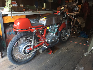
After popping off the valve covers and checking clearances, I installed new gaskets. Then we put the motor back in the bike. At this point there will be lots work done for attachments for cables, wires and other fittings.

Re-assembly, Part 1

Image
Ran into my first snag while re-attaching to swingarm to the frame. I had an extra set of lugs welded on for the Tarozzi rearset footpegs I plan on using. I had decided to have them welded on top of the existing lugs this allowing for footpegs of different threads to be used. Unfortunately, the clearance between the swingarm and the newly welded lug was a bit too close when the bike was on the center stand and the shocks were fully extended.  So I ended up having to cut a bit of the new lugs; fortunately there was enough room since the footpeg did not the the full length of the new lugs. The re-assembly will continue for a while - luckily I haven't run into any other issues for the rest of the day, but there's still plenty more work to do...

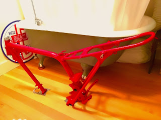
Frame is Done

Image
Finally, bike re-assembly starts tomorrow.

Frame prep & painting

Image
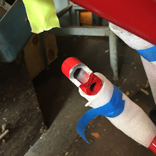
This is the one part of the project I dreaded the most - painting the frame. After receiving rather outrageous quotes from local shops to sandblast the frame, I then resorted to using the soda blaster myself. When that yielded unsatisfactory results I turned to old-fashioned sanding by hand, accompanied by a palm sander for the top tube and other accessible spots. I also used a Dremel with various bits for some nooks & crannies.

Forks

Image
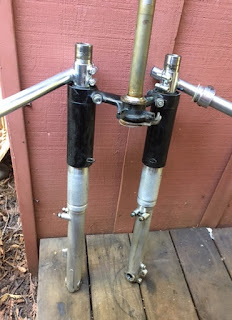
I took apart the forks to clean and polish. These forks have a stamp that indicates date of manufacture on the inside bottom leg. These were made September 1966: After cleaning and polishing, I also repainted the black dust sleeves in bright silver with black trim. After installing back on the frame they will be filled with fresh 20-weight fork oil.

Tachometer Mount

Image
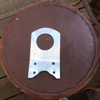
I made a mount for the Veglia Tachometer out of sheet aluminum. It's just a mockup of what I want to make out of thicker gauge at a later point. But for now, this should work.

New Tank

Image
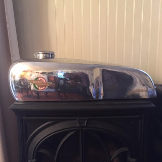
The tank that I will use for the bike finally arrived, after a two-month wait. It certainly looks great, but I was disappointed to find out that the bungs that were welded onto the bottom had male instead of female threads, and the opening was also much too large for the original OMG fuel petcocks I had planned to use: The decision was made to have a friend weld a piece of aluminum stock in the existing hole, then I would have to drill and tap the correct thread: At this stage I'll wait until the bike is further along in the assembly process, and if needed I will use gas-resistant thread seal to protect from leaks.
Fenders and Seat

Image
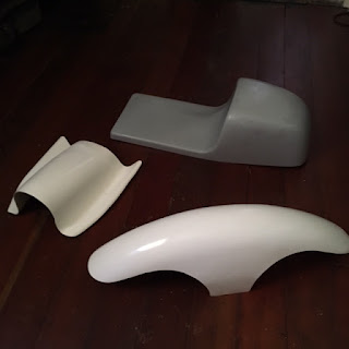
I sourced the fiberglass components for the bike which consist of the front and rear fenders as well as the seat cowl. The fenders came from Air-Tech Streamining in Vista, CA and the seat was ordered from Europlast in Gambettola, Italy. In attempting to be period correct, I planned on using nitrocellulose paint for these parts. I ordered two different shades of red; Dakota and Fiesta red. Both were used by Ford in the 1960's and coincidentally were also used by Fender Guitars at the same time. I sprayed both colors to see how they would look in person, since color samples shown on the vendor's website couldn't be trusted. On the left is Fiesta Red and the Right is Dakota Red: In my opinion Fiesta Red was too orange and Dakota Red had too much purple. After  searching around for a bit, I finally ended up going with contemporary Ferrari Red. I'm pretty happy with the result: Next on the list is to make a frame for the seat cowl pictured above. I plan o...